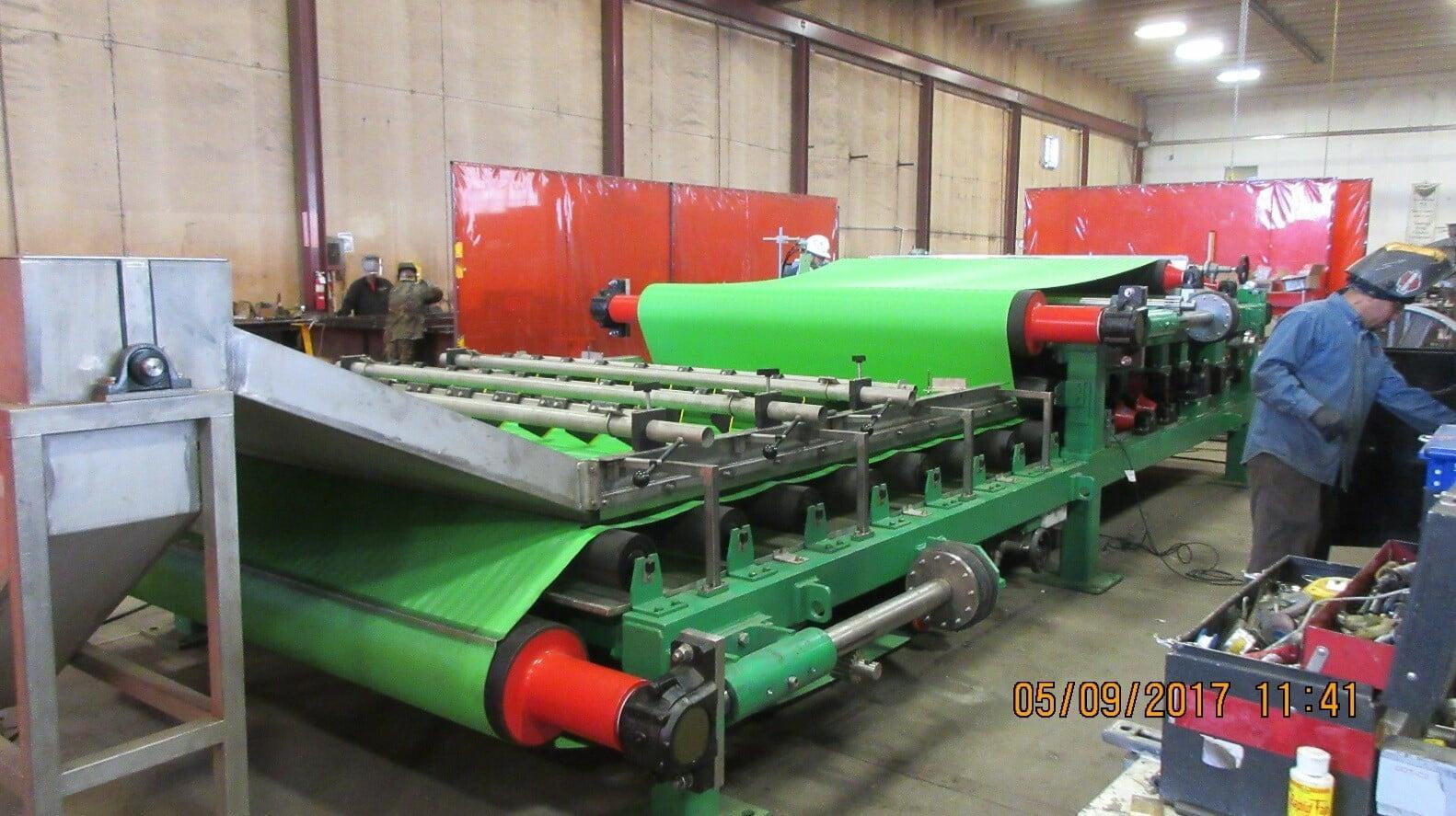
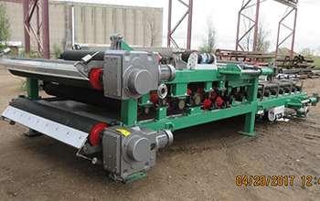
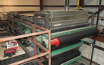
Belt Press
WSI has been designing and building Belt Filter Presses for over 12 years. Our belt press uses industry standards as well as proprietary technology. All of our presses have five major components; a headbox for optimal sludge flocculation, a gravity section to thicken the sludge, an adjustable wedge section to allow for maximum dewatering, an “S” section to permit a gradual increase in pressure and a cake doctoring section to remove the sludge from the belt. Each section is custom designed to meet or exceed the demands of the project.
WSI Belt Press Designs
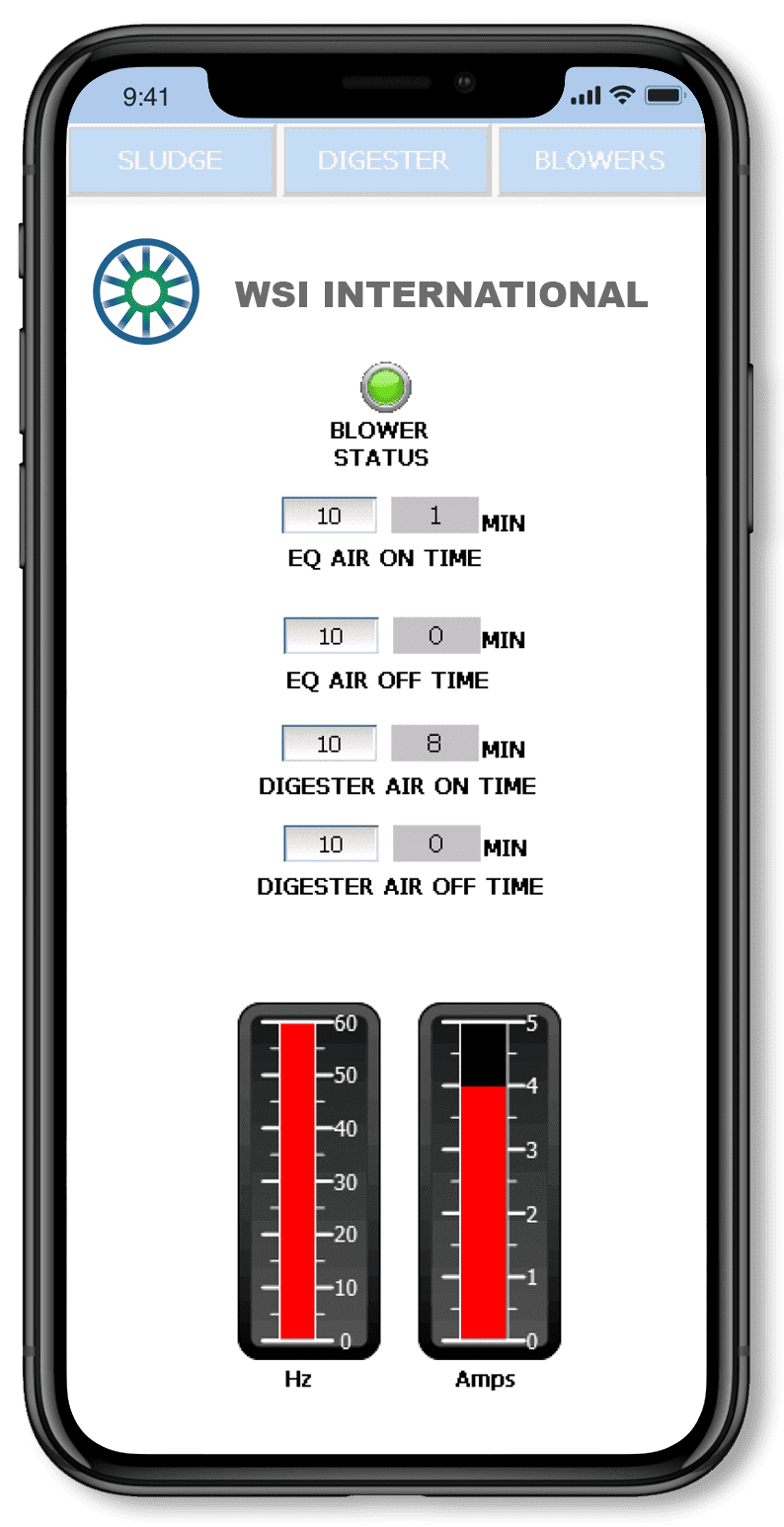
Electrical & Controls
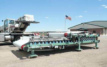
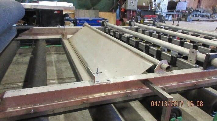
Extended Gravity Section
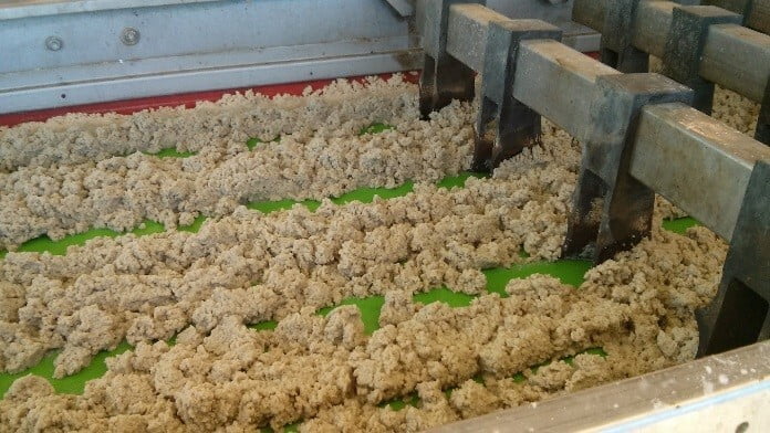
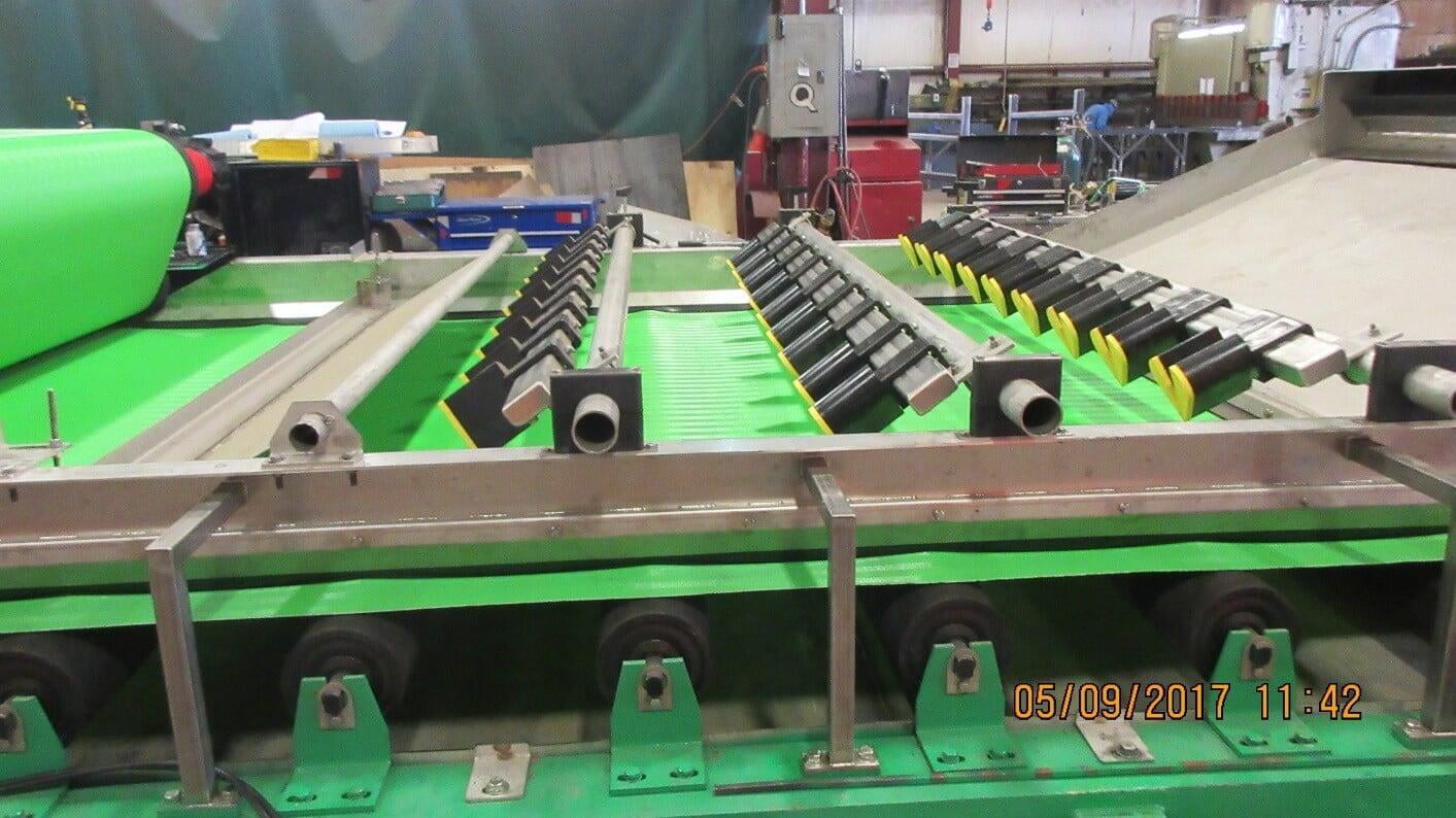
The Extended Gravity Section allows the flocculated sludge to drain. The belt in this area is supported by 6” diameter rolls in lieu of a traditional UHWM deck. The rolls on the gravity deck offer three major advantages over UHMW wear bars. First, the rolls wick water from the belt and speed drainage. Second, the friction between the belt and the gravity deck is significantly reduced, extending the life of the belt. Third, the downtime associated with replacing the UHMW wear bars is eliminated. Arrays of chicanes are positioned along the length of the gravity section. The chicanes clear belt area and corn row the thickened sludge allowing further thickening and drainage. An adjustable leveling plate smooths the tops of the corn rows into a sheet prior to entering the wedge section of the press.
Flocculation and Distribution
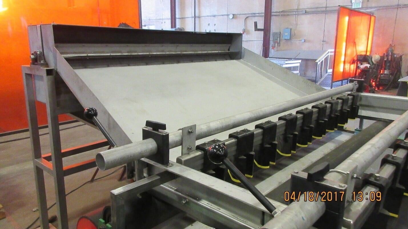
Polymer is injected on the discharge side of the sludge feed pump through a four-port ring injector with adjustable mixing intensity. The ring injector provides for rapid mixing of the polymer and thickened sludge. Flocculation begins to occur in the sludge pipe and further develops in the up-flow flocculation box located on the front end of the press. The flocculation box has a conical bottom that slows the velocity of the incoming sludge. A distribution paddle continuously moves thickened floc from the top of the floc box and down the distribution chute to the gravity section ensuring equal distribution across the width of the machine.
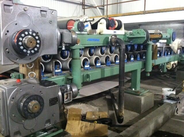
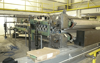
S-Roll Section
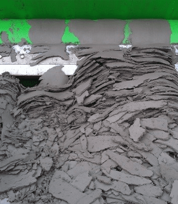
In the S-Roll section, the two belts wrap around the rollers in an “S” pattern, moving from rolls of greater diameter to lesser diameter. As the diameter of the roll’s decreases, increasing pressure is applied to the sludge cake expelling more water with each roll wrap. This follows the same principles throughout the entire machine of ever-increasing pressure and increasing cake dryness. By the time the cake reaches the end of the machine, it has developed into a dry cake devoid of free water that is scraped from the belt by the UHMW doctor blades.
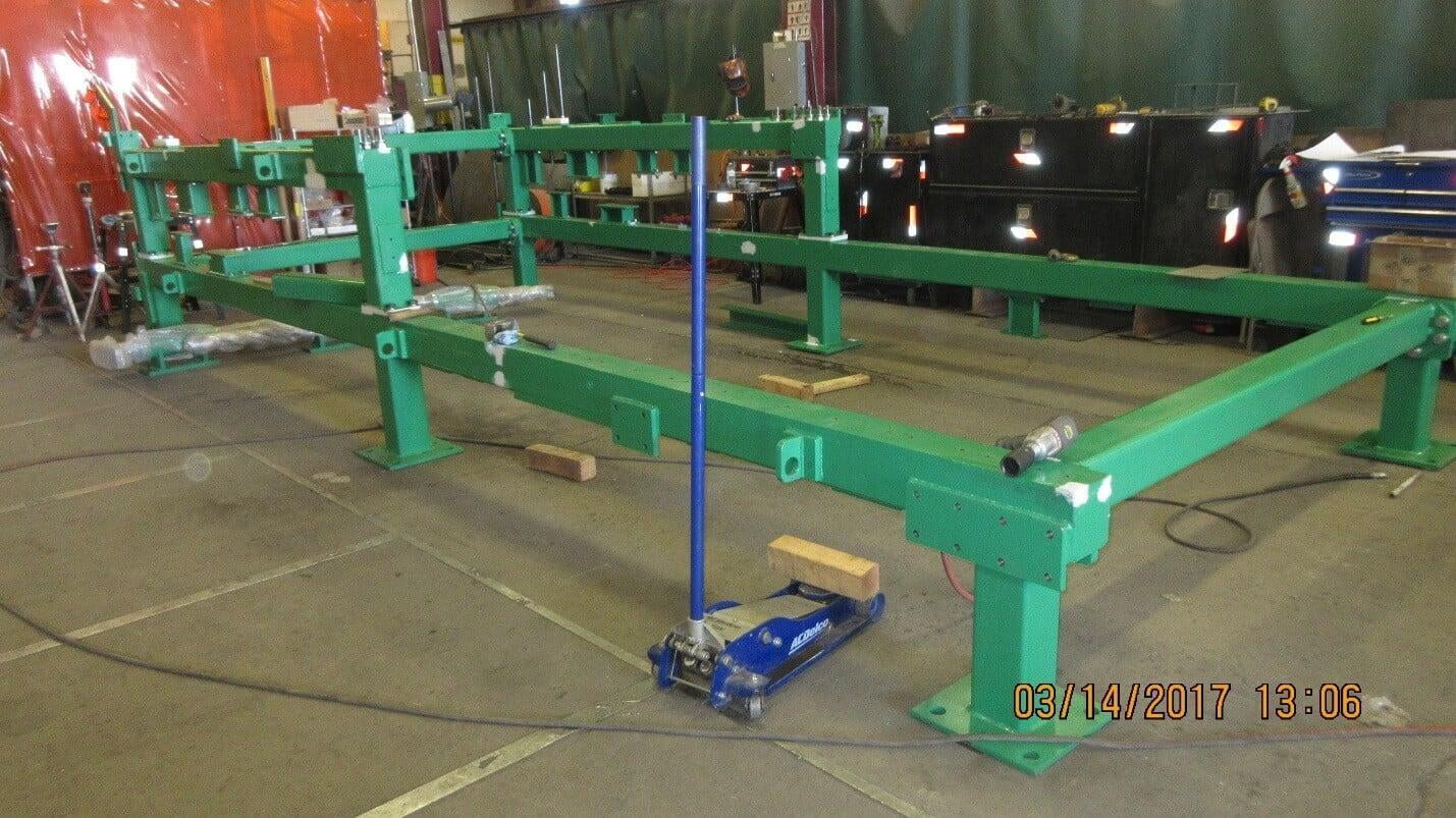
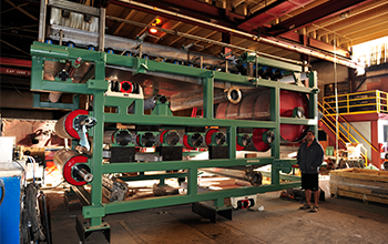
Frame Construction
The frame is constructed from 6”x6”x3/’8” structural steel tubing that is capped and sealed. Drilled and tapped machined plates are welded onto the frame structure to eliminate penetrations into the structure. All cross members are flanged and bolted. Steel channel, angle and I-Beams are never used in the frame construction of a WSI press. Channel and angle have poor torsion characteristics, and all are prone to the accumulation of water and sludge which accelerates corrosion of the structure.
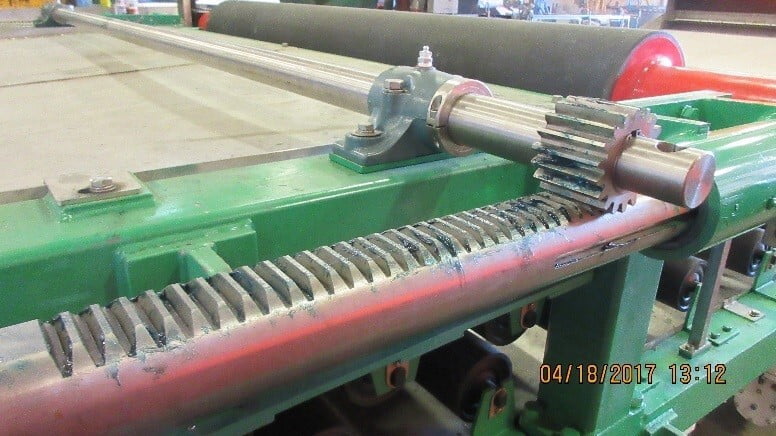
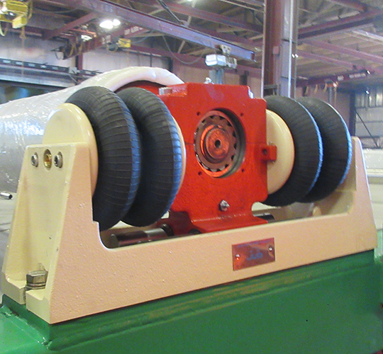
Rack and Pinion Tensioning System